
SUMMARYAn existing 3/4" aluminum reinforcing plate that was bolted to the back side of the slightly sagging wooden mast beam was removed. The delaminated wood beam was jacked up, and four red mahogany knee supports were sistered to the forward bulkhead. The old aluminum beam was repositioned closer to the cabin ceiling, and a new 5061 3/8" aluminum plate was added to the front of the beam in the V berth using longer galvanized bolts. (See photos below.) PLANNING THE WORKThere were three primary information sources consulted for this reinforcement plan.
SKILL LEVEL AND TOOLSThis repair required little beyond the basics with regard to specialized skills or tools. Neither finesse nor fine woodworking skills were needed, though greater experience and higher standards will, as always, result in a more pleasing final product. The basic idea was to support the beam: a number of ways to do that could be dreamed up by the imaginative. The project was more time consuming than technically demanding. TIMEA few hours were needed for rounding up supplies and parts. Sawing and shaping knees and drilling holes used up a couple more hours. Finally, a couple of days (roughly four or five hours each) were needed on the boat for installation work. THE PERFECT FIX?The goal was to slightly raise and to better support the mast beam on an older, pre-liner Alberg. This appears to have been accomplished, though time will tell. A more rigorous, invasive fix-- perhaps the perfect fix-- may perhaps be to excavate the original delaminated beam, build a new one, replace it, and beef up supporting posts. Such effort was not necessary in this case. While a typical mast beam repair on these older boats sees the addition of through-bolted aluminum plates to each side of the mast beam, it may be argued that downward forces on the beam are most simply countered by adding supporting posts (or knees) alone. Particularly in the case of boats with the earlier laminated wood beams, metal plates don't necessarily provide as much vertical support as do posts. The plates would seem to offer mostly fore-and-aft support with only a secondary amount of vertical support. COSTS
 BEFORE: Viewed from the V-berth this sagging of the mast beam appeared to be around 1/4 inch, presumably since the boat was built in 1967-- that was, if the white paint line was used as a guide. It was later found, though, that the rabbeted fascia board over the center of the doorway easily slid up and down a short ways once the bolt was removed.  A previous owner had installed this 3/4" aluminum plate over the after side of the beam at an unknown date. These fasteners were 6" x 1/2" galvanized bolts which showed no signs of corrosion. Starboard side view. 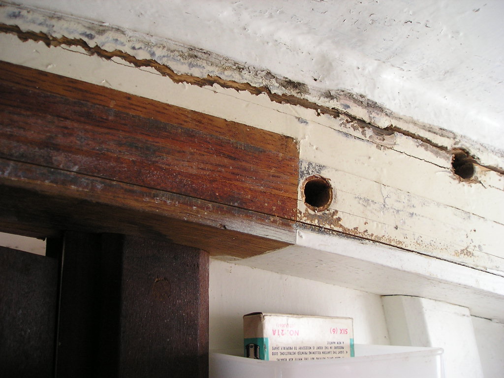 DURING: The first step was to remove the existing aluminum plate for a look-see. Under the beam was the laminated wood beam with 1/2" bolt holes. The beam was 3 and 7/8 inches wide. The horizontal cracking may indicate some separation of the beam from fiberglass tabbing though everything appears sound. 
 View of port, aft side of the beam. (Clear plastic hoses are holding tank vents ending inside the cabin top dorade.) 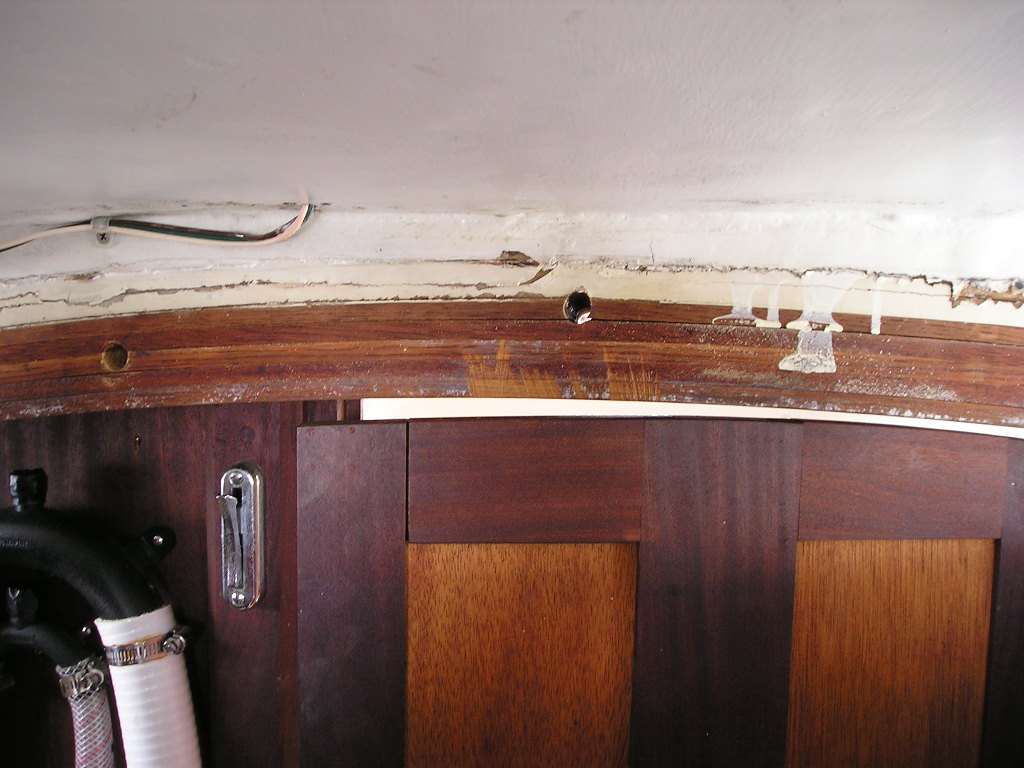 Aft end of the mast beam over the door, looking forward. Laminated 1/2" boards making up the beam can be seen.  Looking forward into the V-berth. After slacking off shrouds and stays three or four boards were laid on the sole in order to distribute weight from the hydraulic auto jack. Doubled 2x4s with a block at the top worked fine to raise the beam. There was no need to follow a protracted time table with this lifting. The beam went up readily. Quiet, eerie cracking sounds signaled too-rapid or too-far lifting. 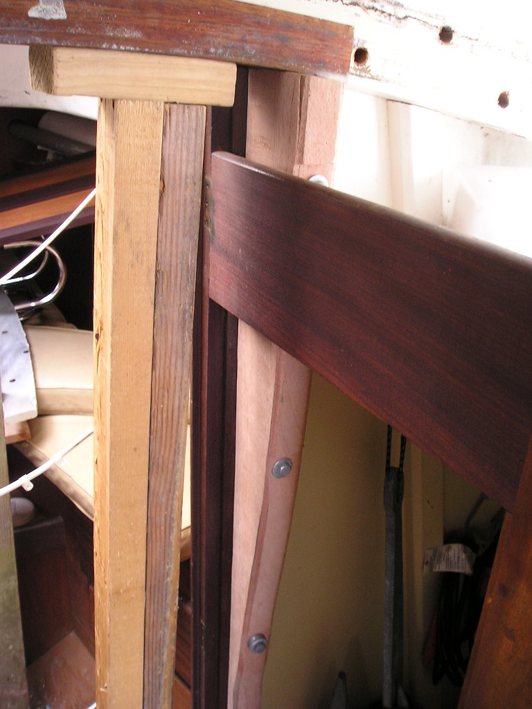 To my mind what was needed the most were supports under the beam to support it and to prevent future sagging. These seemed more significant that the aluminum plates. With the jack in place I added four knee supports, through-bolting them onto the existing lightweight posts originally secured to the bulkhead. (The forward bulkhead was 3/4" veneer plywood, the after bulkhead-- through which this photo was shot-- was 1/2" veneer plywood.) The knees were 2" thick red mahogany, 4" wide at the top tapering to about 1" thick at the bottom. Inner knees were four feet long, outer ones were 30" long. The wood was cut and routed at home. Fasteners were 3/8" galvanized metal bolts varying from three to five inches in length. 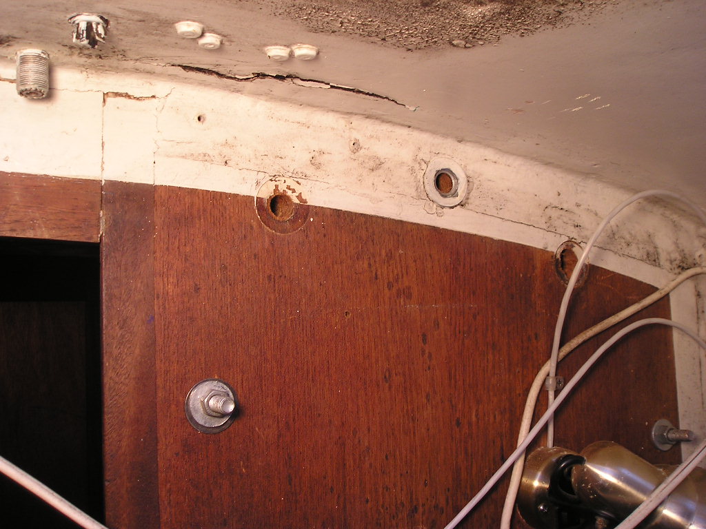 View from the v-berth, port side, once the knees were in. Note the SS fender washer plus a galvanized 3/8" washer on the through bolt. The white paint line across the fascia board and bulkhead is correctly realigned though, given the loose fit of the fascia board, this may not be so important.  Port side knees in place.  Top of the port side knee meeting the bottom of the beam. 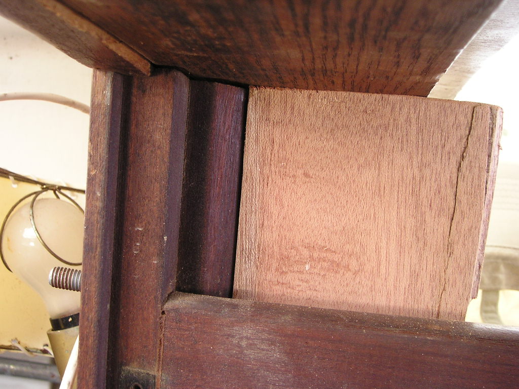 Top of the starboard side knee meeting the beam. (Please ignore that little splitting-off piece!) These are 4" wide at the top: the original plan was to have them directly supporting the aluminum plate. That didn't work out-- and it isn't really needed. The knees were left extra wide but could be removed and trimmed back any time.  The original 3/4" aluminum plate was reused, but was placed higher up. It was flipped in order to allow new bolt-hole placement. (They weren't symmetrically drilled into the plate the first time around.) Holes in the starboard locker shelf were cut out with a saber saw to accommodate the new knees. 3/8" drill holes first cut in the shelf gave a starting point for the saber saw blade. When drilling holes through the outer knees and bulkhead on both sides I hit metal and so had to drill a new, second hole. I don't know what the metal was-- it appeared to be inside the bulkhead.  It seemed a good time to add a second aluminum plate into the mix. The V-berth plate is 3/8". The piece it came from cost $56. A local shop cut out the arch shape with a bandsaw following the lines I drew on it. (Those with higher standards would make a cardboard template cut to fit the beam. A precise drawing of the template can be scanned and the metal cut by computer laser.) Longer bolts were required. I stuck with galvanized bolts, washers and nuts since the former ones had held up fine. New bolts are 7" x 1/2" and cost about $12. The work of artist Frank Stella and his sculptural plate-aluminum paintings have always been inspirational. Here was a chance to give it a try with the grinder. 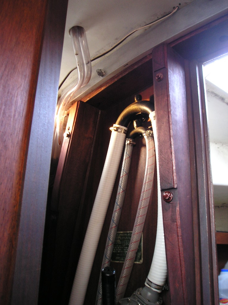 AFTER: A wood stain, "red mahogany" by color name, did a fine job of making the new knees look like the older wood. (See below, too.)  A hoped-for outcome was that the head doors would close again. They did close, tightly, five years ago, but have since tightened up. During this operation the forward bulkhead was jacked open with a small auto jack. There was no movement, however, which eliminated the adrift bulkhead theory What would cause the doorways to narrow so the doors would no longer close? It's not clear. In the end a saw was used to trim the swinging vertical edge of the door, which now closes; it's a displeasingly less than elegant solution. Please support these businesses that support the Alberg 30 Association: 


|
|