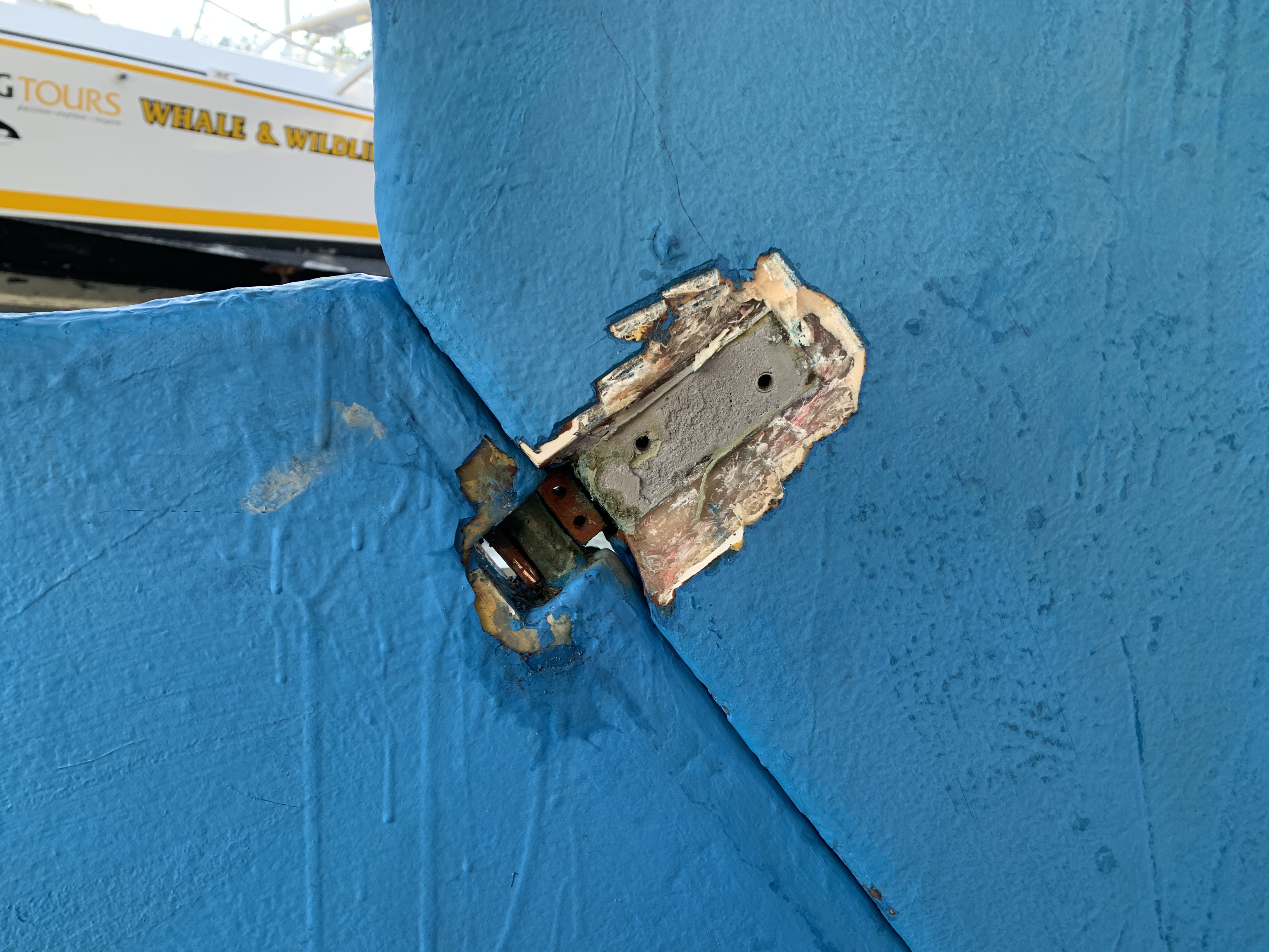
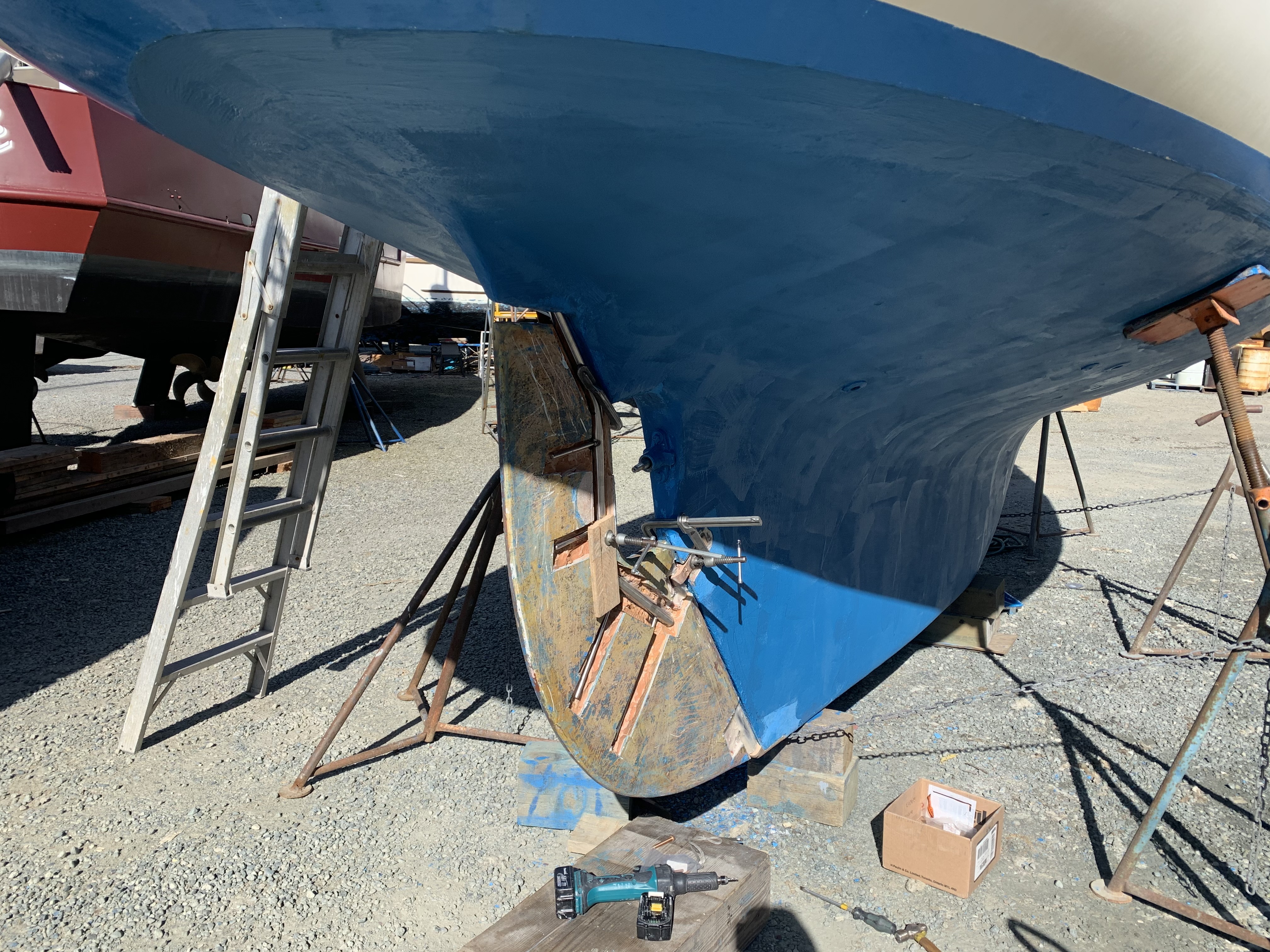
The problem
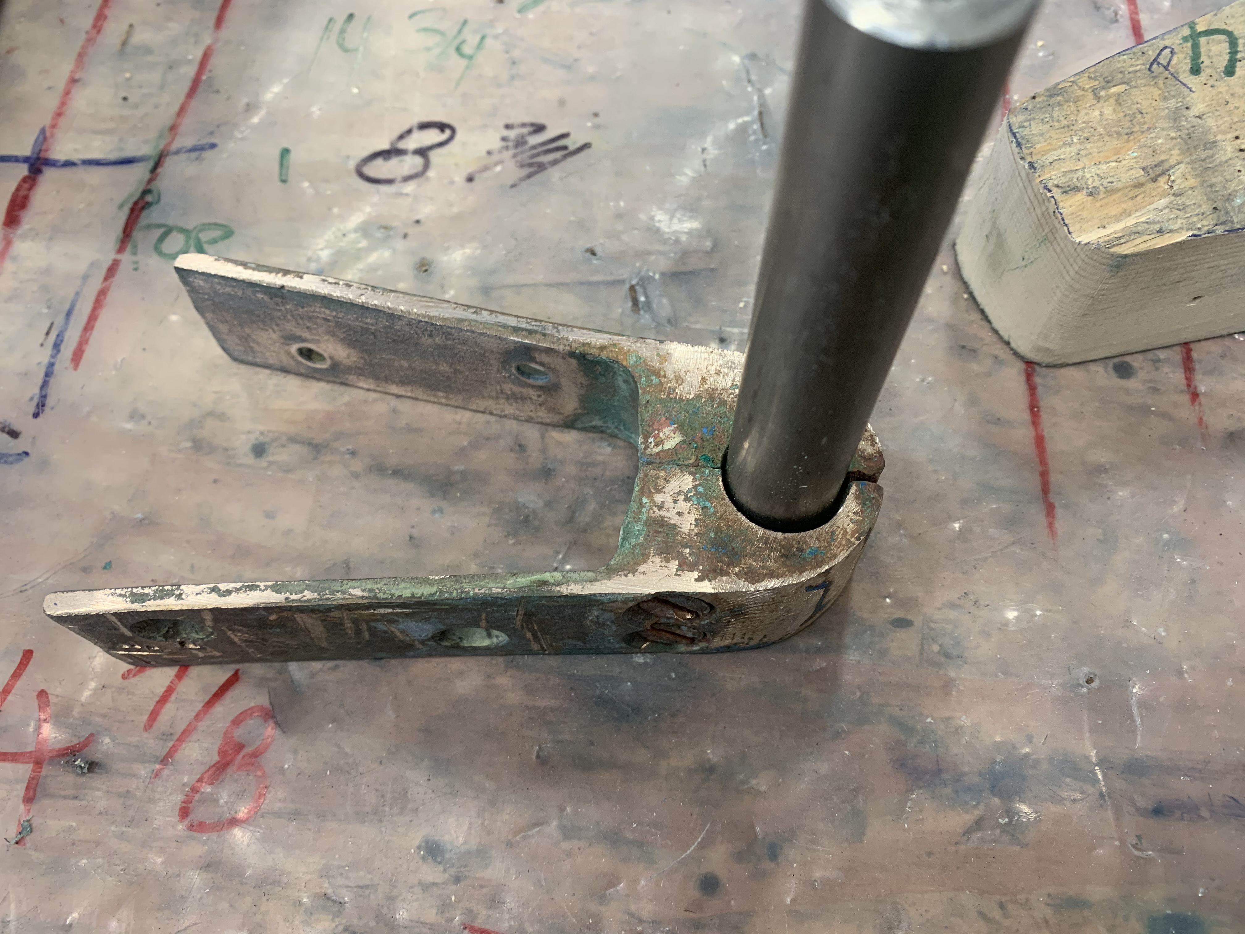
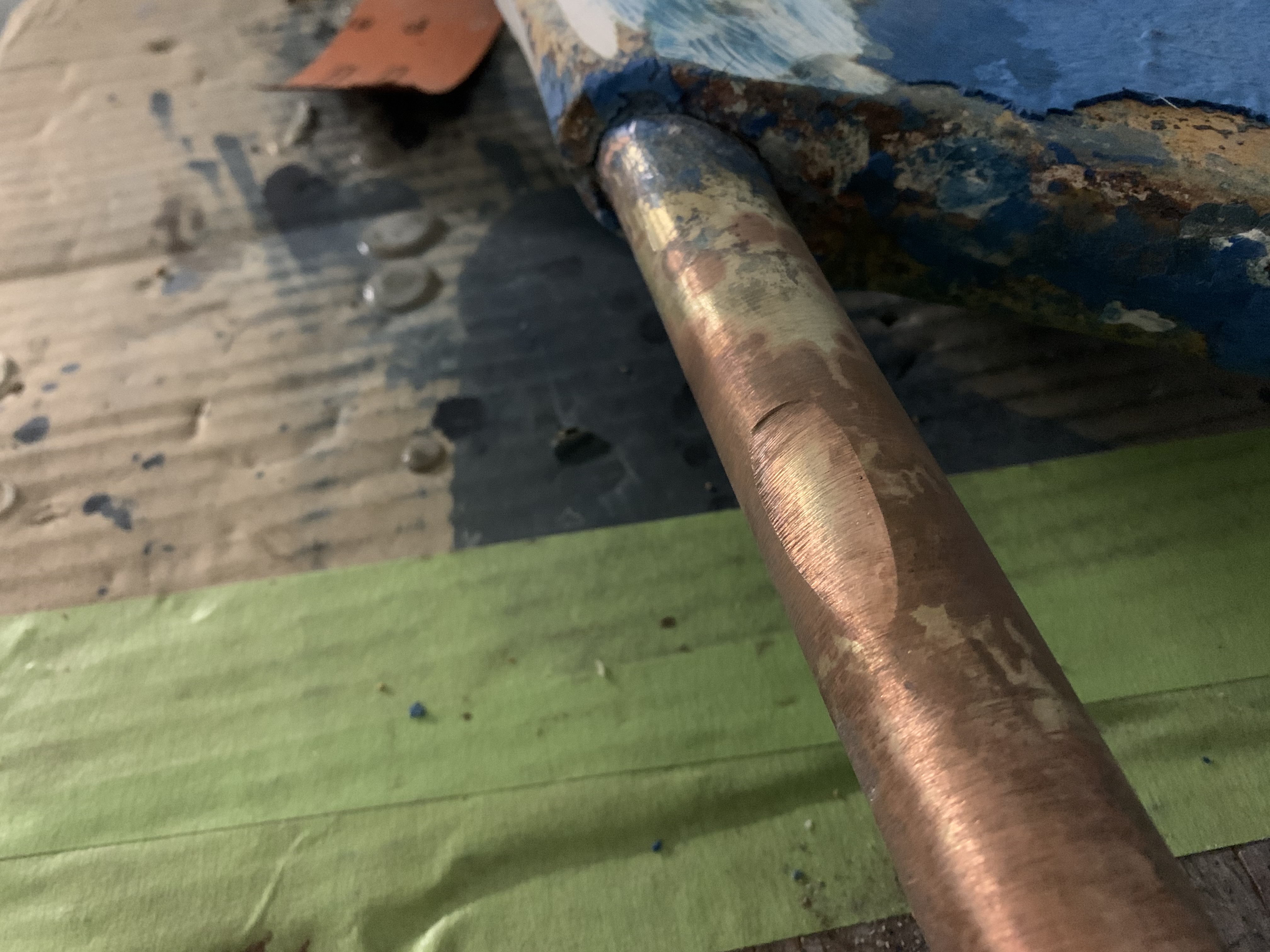
If there was a bit more pin, the solution is just to make a bushing to fit between the hole in the rudder shoe and the pin. But this pin was too far gone for that. The second solution is to cut out the pin, drill and tap a hole in the bottom section and screw in a new pin. I might have done that if there hadn't been other problems.
There was maybe a quarter inch of good metal left, and even that was compromised with a bit of de-zincification running right into the centre.
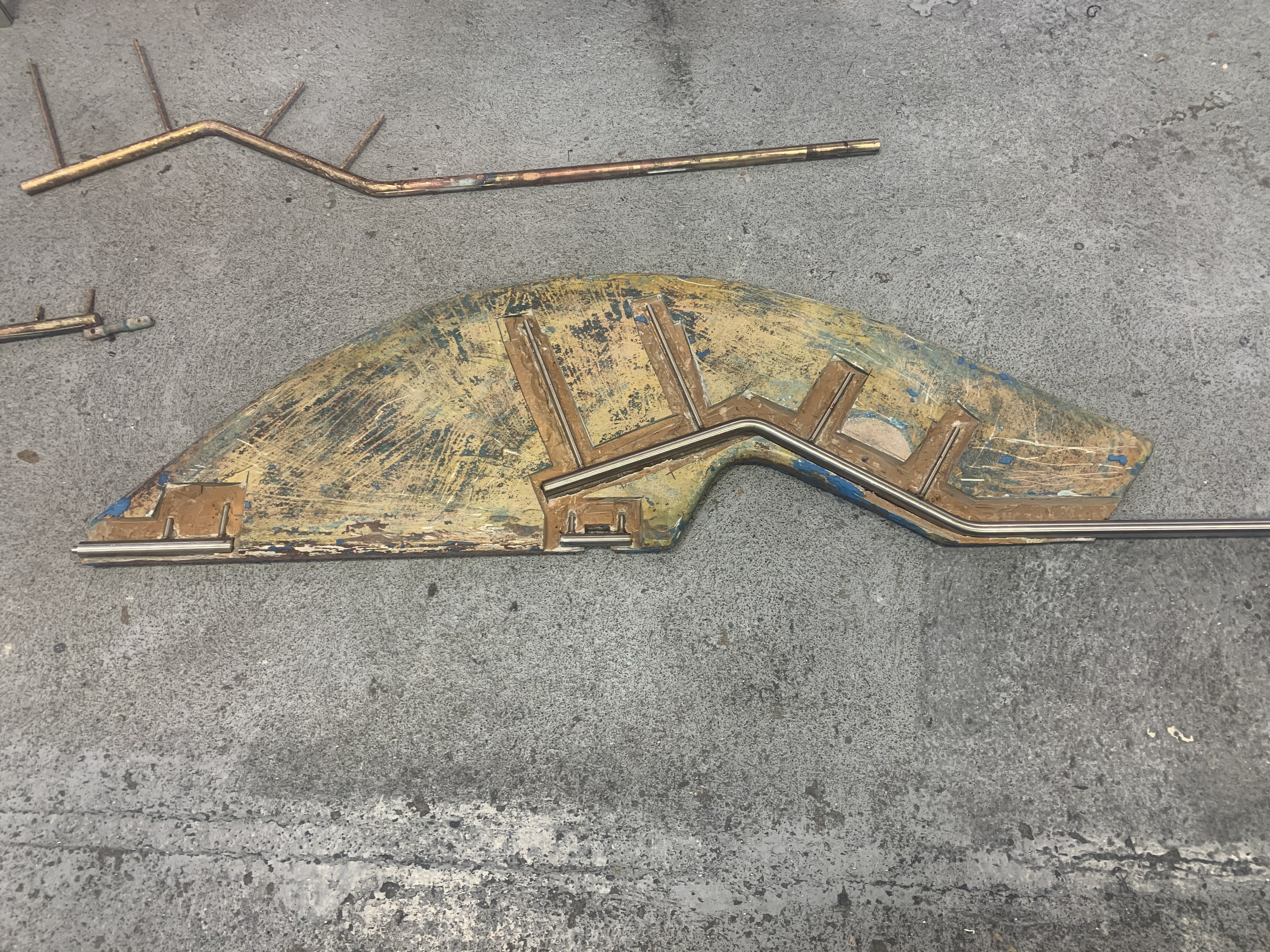
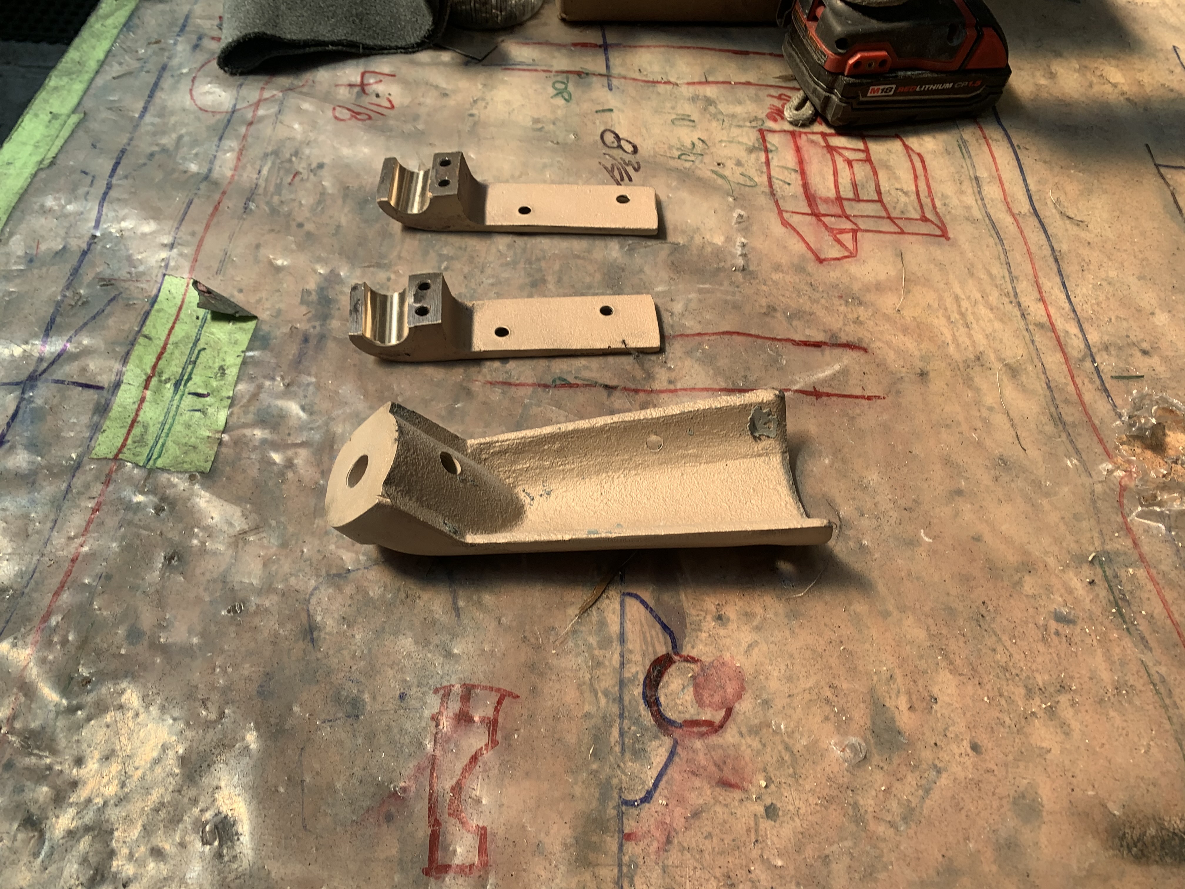
My boat is a 1972 boat, #495. Some of the following my not be relevant to your boat. The rudder shaft was in 3 parts.
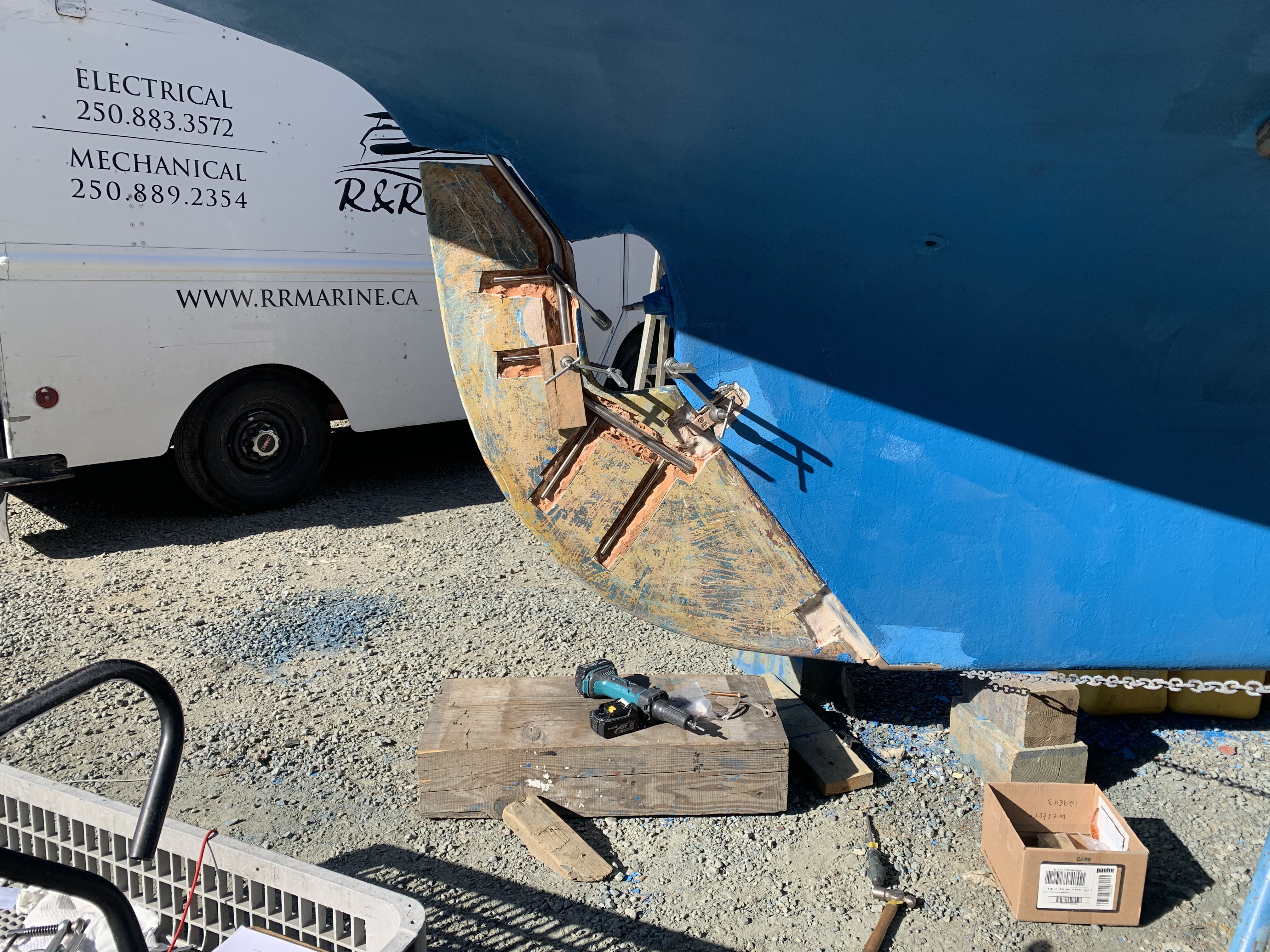
The thin spurs coming out of the top section are largely ornamental. They're quite thin. The torque from the tiller is transmitted to the rudder because the 1-inch upper shaft has bends in it, not because of the spurs, which can be bent by hand. One the two smaller bits, the spurs stop the part from spinning with the rudder. One the midpoint section the brazing had failed. On my boat, the 3 parts were not correctly aligned. The midpoint section was 1/8 inch out of column with the top and bottom sections, probably because it's thinner (3/4 inch) and whoever put the rudder together back in 1972 lined up the sides of the parts, not the centres. All in all, it was pretty obvious that the rudder needed to be removed and all the metal replaced. Removing the rudderAt least one Alberg has a bolt on rudder. I don't. Removing the rudder was a lot of work. First off, the propellor shaft blocks the rudder from dropping down. That meant either pulling out the propellor shaft altogether or moving the engine forward 2 inches and pushing the propellor shaft forward 2 inches so the rudder can clear the end. The first option mean removing the coupling from the engine and also removing it from the shaft. I was advised that removing the coupling from the shaft would be a lot of work in a very confined space, so I went with moving the engine forward. It was also a lot of work. I'm still not sure that was the way to go. Actually, I am sure, because it revealed that two of the bolts holding down the engine were rusted out, which I wouldn't have found out otherwise. But if there hadn't been any other problems, I think it's about 50-50 which way to go. Because the engine only had to be moved a few inches, it was really only a question of removing a few bolts. Most of the hoses and wires could stay in place. Next problem is that access to the rudderpost stuffing box was needed. On my boat, this is behind and under the gas tank. I've removed the gas tank on two previous occaisons, so this step was fairly straightforward, if annoying. I removed the wooden bulkhead between the engine compartment and the starboard cockpit locker. The first time I did this, it took a while because I was nervous about wrecking the bonds between the fibreglass and the wood. But when I put it back, I just screwed everything back together so it's relatively easy to remove, as long as you don't mind spending an hour kneeling in the cockpit, with your head below knee level in the cockpit. There are people who will tell you that the way to remove a rudder is to dig a hole under the stern of the boat while it's on the hard. I'm not sure how that would work. The rudder post is at an angle, so you would have to dig the hole under the aftermost part of the keel, leaving it unsupported. Anyway, the yard frowns on hole-digging and lifted the boat to drop the rudder. At this point, it was discovered that the packing in the rudder stuffing box hadn't been put in correctly and was leaking slightly. Rebuild

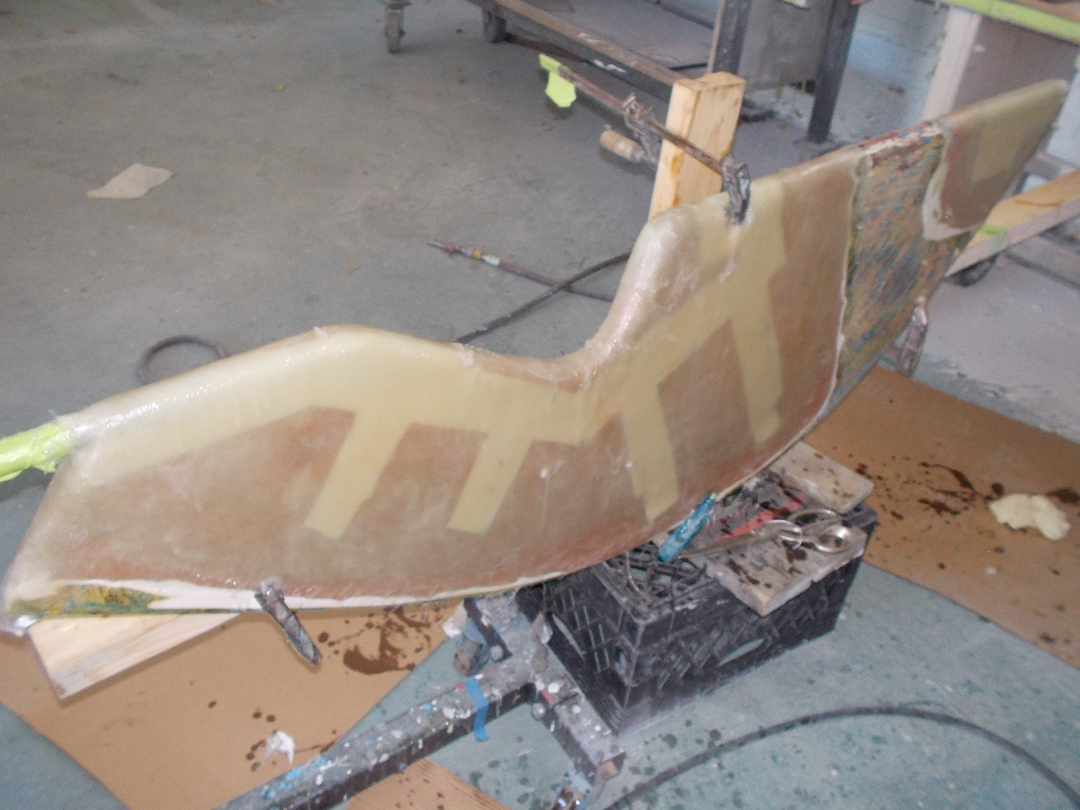
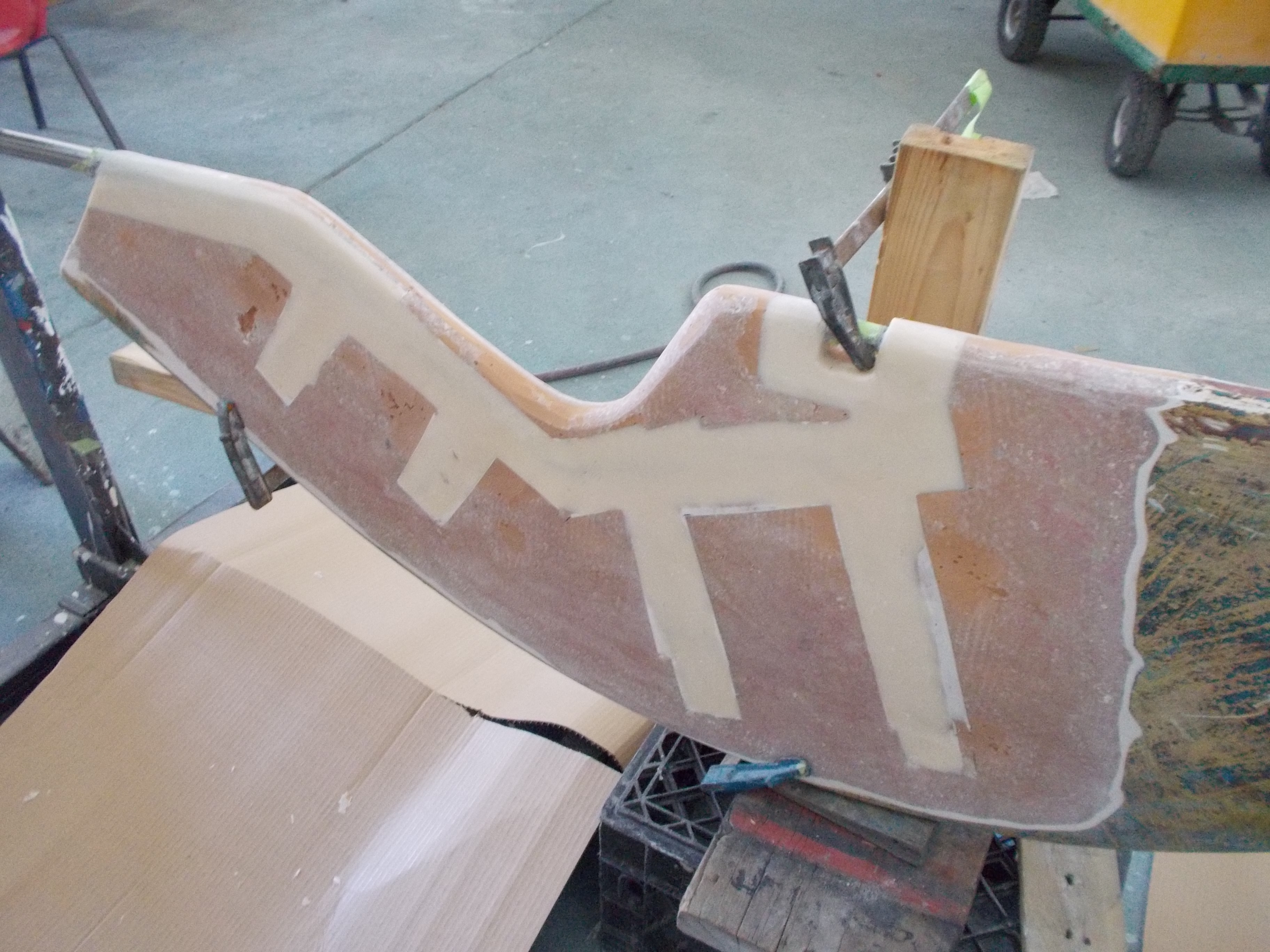
I left all this stage to the professionals. I simply did not have time and space to do this. I also don't have the tools to bend 1-inch stainless rod, or weld. But as you can imagine, it wasn't cheap. The result is, however, better than new. Stronger, and built to a higher precision than Whitby Boatworks did when they built the boat in the first place. The reinstallion was pretty straightforward, with another lift of the boat, and inserting the rudder. Note that the screws that hold the rudder shoe actually penetrate the hull, at least on my boat. The yard guys says he sees this a lot on full keel boats. When they're being built, getting all the glass and resin in to the very bottom behind the deadwood sometimes doesn't happen as well as it should. The upshot is that those bolts need to be properly sealed. Then a few hours of work getting the gas tank back in and the bulkhead re-installed. More Photos


|
Please support this business that supports the Alberg 30 Association: