|
Recently, when I bought my Alberg 30 (formerly "Cold Duck", hull# 39 built
in 1964) I knew that damage to the wooden rudder would require repair or
replacement of the blade. Since the boat is currently in Ontario and I live
in Newfoundland the damage was a potential factor in deciding how to get the
boat to her new home port. Initially I thought that the rudder would have
to be replaced but I discovered that the damage is not as bad as it seems.
Since the majority of the wood is still sound, a temporary repair will allow
me to sail the boat home in 2007 where I can make the necessary permanent
repairs. I will decide then whether to repair the present rudder or use it
as a pattern for a new one built from GRP.
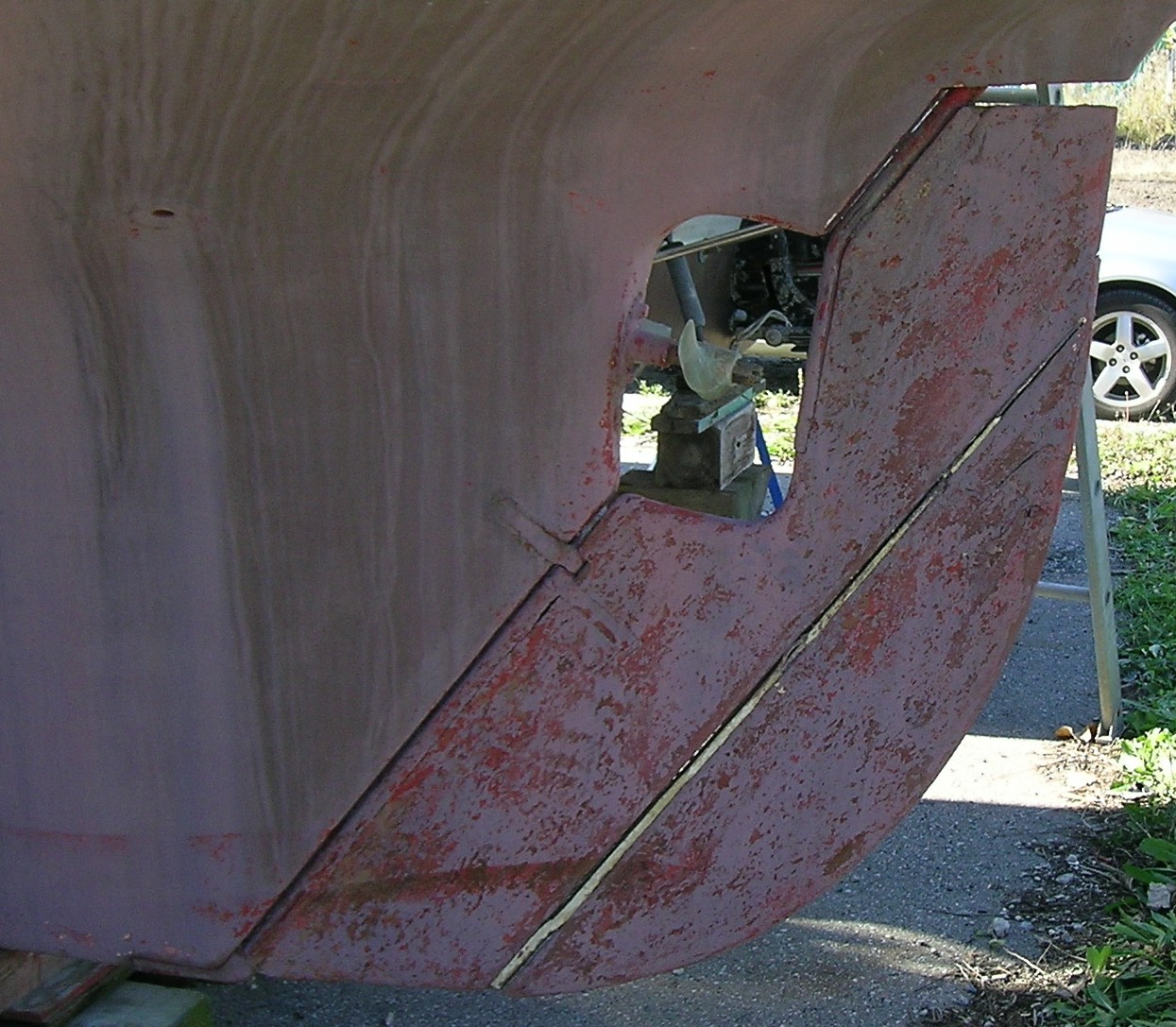
It is apparent from the Maintenance Manual and also discussions on the list
that there is some variation in how the Alberg 30's rudder is attached to
boat. The consensus seems to be that the rudder can only be removed by
removing the tiller head and the shoe on the keel and dropping the upper
shaft through the hull. What is not clear is whether the earliest rudders
were mounted the same way as the later rudders. There was a suggestion that
one early rudder was attached to the upper shaft by rods that could be
removed from the leading edge. I was hoping that because mine is an early
boat that the blade could be removed without going through the process of
removing the shaft as well.
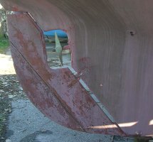

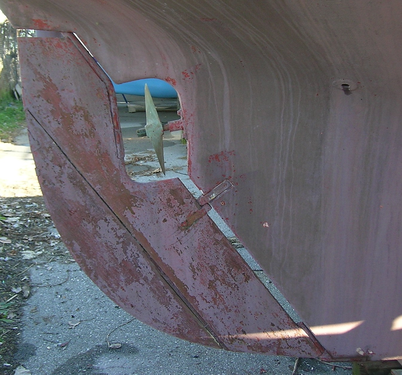
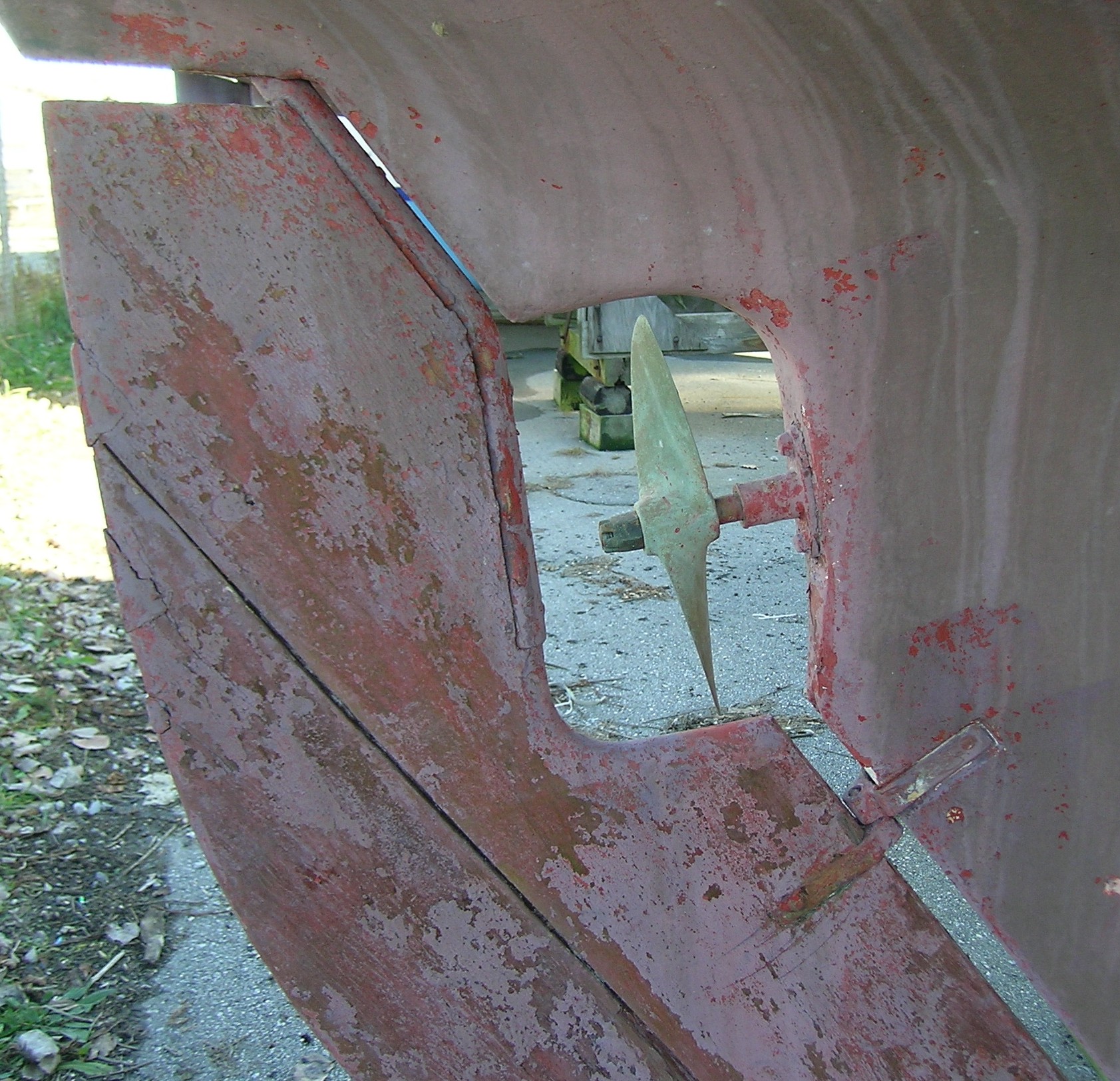
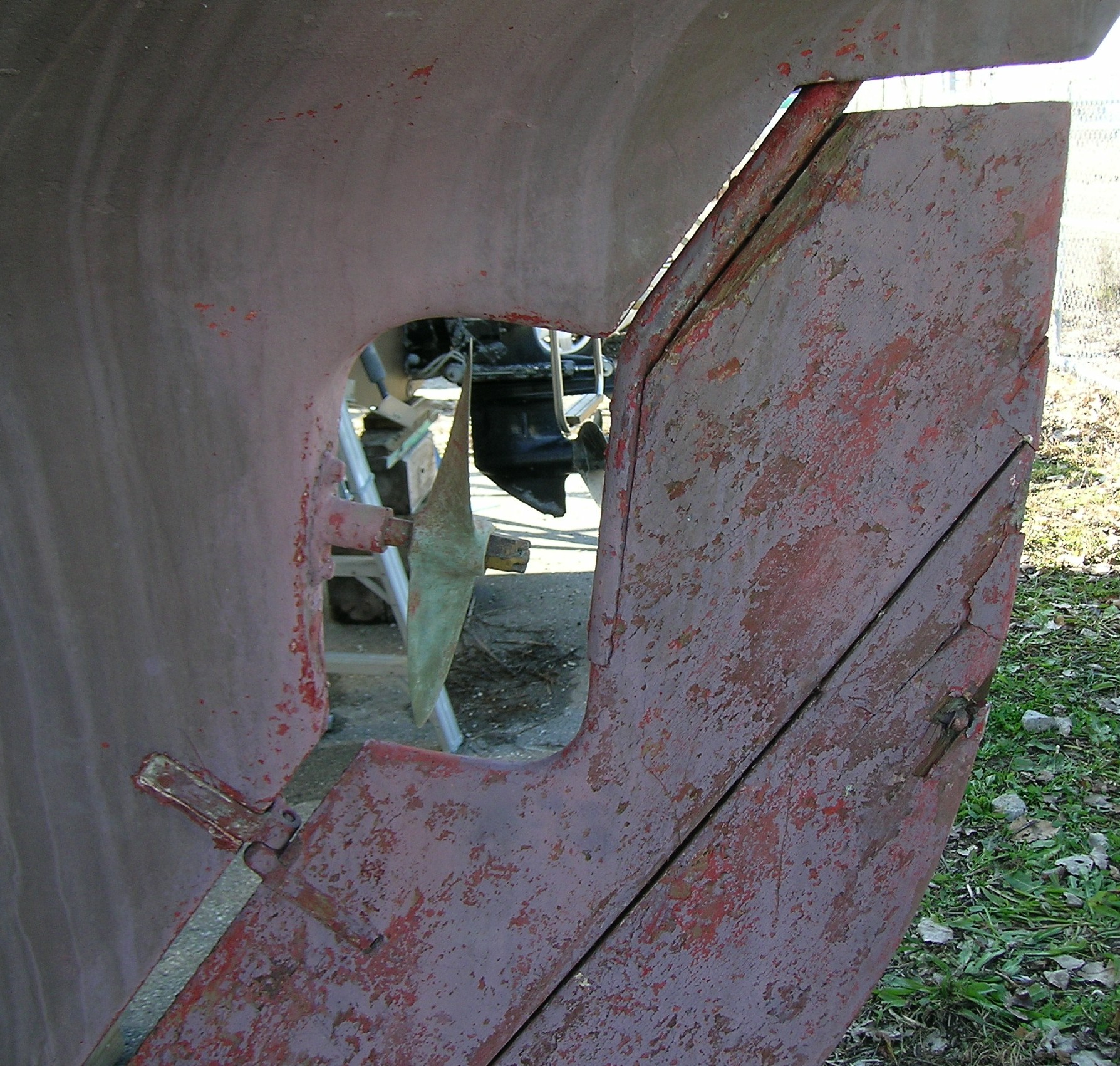
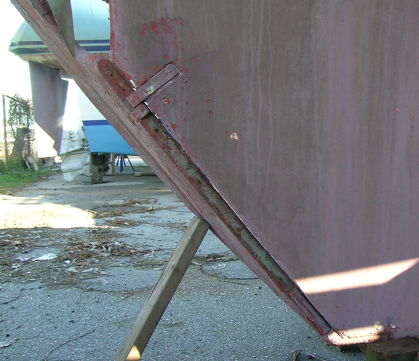
Removing the braid/caulking and cleaning the seam allowed the gap to be
substantially reduced (Photos 3 & 4) by tapping the trailing edge of the
rudder with a piece of 2 X 4. I suspect that the gap can be further reduced
using clamps. As has been mentioned in the Maintenance Manual, and on the
list, the rudder blade is attached to the two rudder posts by bolts of
various lengths which run to the trailing edge of the blade and terminate
with washers and nuts. Closing the seam revealed that the nut on at least
one of the upper shaft bolts (the lowest one) had been "dragged forward"
into the wood of the blade. This had created an apparent "blister" in the
wood surface. The surface of the "blister" was easily removed but it and
the surrounding wood did not appear to be rotten. This damage can be seen
in Photo 4 on the trailing edge of the blade opposite the bottom of the
upper rudder shaft.
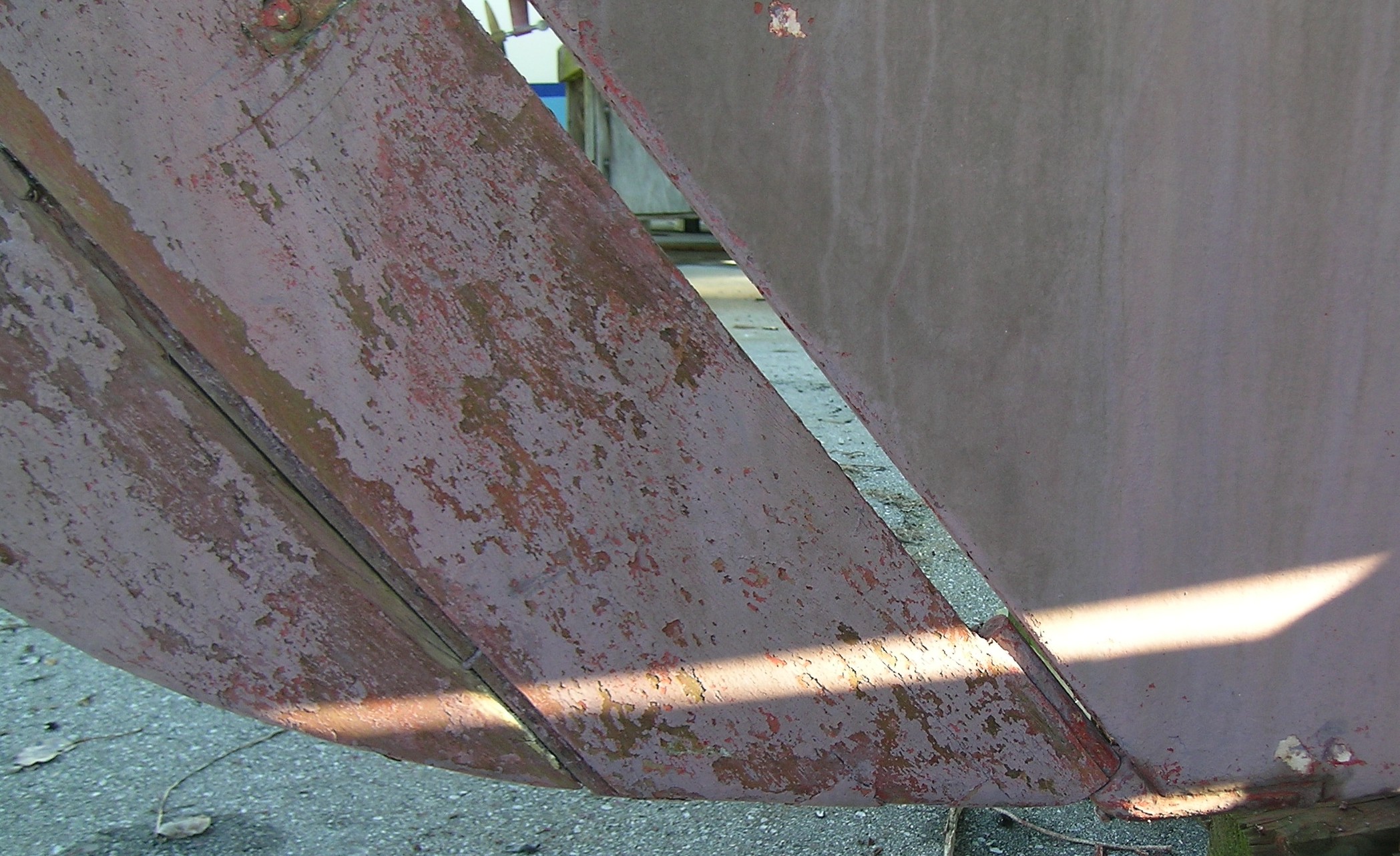
The leading edge of the lower half of the rudder is not a continuous shaft
as it first seemed but is a combination of pieces of wood trim, a pintle and
gudgeon and a short lower shaft that inserts via a pin into the shoe on the
keel. The two pieces of wood "trim" were barely held in place by rusty wood
screws. Both pieces of trim had been manufactured using a router bit to
create a semicircular leading edge to the rudder.
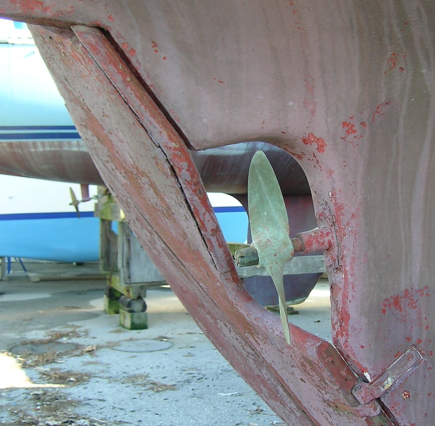
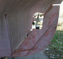
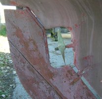
With the trim pieces removed, photos 5, 6, 7 & 8 clearly show the mounting
hardware that attaches the rudder to the hull and shafts. An examination of
the trailing edge of the blade shows 5 triangular pieces of a hard filler
material that cover the nuts at the end of the various rods. By extending
lines from them so that they form a perpendicular with the shaft it is
possible to locate the heads of the rods. Photos 9 & 10 are close ups of
the top and bottom of the leading edge of the rudder with the blade turned
almost 90 degrees to port. In Photo 9 three carriage bolt heads can be seen
in the leading side of the upper shaft. Without digging into the blade it
is not possible to say whether the rods are threaded for their entire
length. In Photo 10 it seems that the rods that attach to the lower shaft
do not pass through the shaft but may be blind threaded as mentioned in the
manual.
Looking at the way the rudder is currently mounted it seems to me that it
could be easily removed without dropping the upper shaft down through the
hull. The first step is to remove the nuts from the three rods holding the
blade to the upper shaft. If the rods are threaded through the shaft it
should be possible to back them out. If they are not threaded then they
should pull out. The rudder needs to be turned hard to port or starboard to
accomplish this step. Next remove the two pieces of wood trim from the
lower portion of the blade. Then the fastenings that attach the pintle to
the blade need to be drilled or driven out. Finally by lifting the blade a
couple of inches and pivoting the top to the rear it should be possible to
remove the bottom pin from the shoe. The rudder would be replaced by
reversing the steps. The pintle would be reattached to the blade using
bolts and nuts to make it easier for future removals.
I am interested in hearing what other owners think of this potential
solution.
Regards,
Hugh McCormack
Woody Point,
Newfoundland
Canada
|
Steering
|